
Configure VXLAN in Distributed Gateway Mode Using BGP EVPN in Huawei Fabric
Distributed VXLAN gateways can be configured to address problems that occur in legacy centralized VXLAN gateway networking, for example, forwarding paths are not optimal, and the ARP entry specification is a bottleneck.
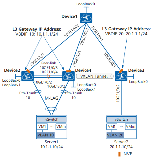
On the network shown in the figure below, an enterprise has VMs deployed in different data centers. VM1 on Server1 belongs to VLAN 10, and VM1 on Server2 belongs to VLAN 20. VM1 on Server1 and VM1 on Server2 reside on different network segments. Server1 connects to the VXLAN through Device2 and Device4. To allow VM1s in different data centers to communicate with each other, configure distributed VXLAN gateways. Device1 is deployed in AS 100, Device2 and Device4 are deployed in AS 200, and Device3 is deployed in AS 300. Device1, Device2, Device3, and Device4 use AS 100 for BGP EVPN.
Configuration Roadmap
The configuration roadmap is as follows:
- Configure EBGP to run between Device1 and Device2 and between Device1 and Device3 and between Device1 and Device4.
- Configure Device2 and Device4 as the root bridge, and configure the same bridge ID for them.
- Configure M-LAG between Device2 and Device4.
- Configure a service access point on Device2, Device3, and Device4 to differentiate service traffic.
- Configure EVPN as the VXLAN control plane.
- Specify Device1 as an IBGP EVPN peer for Device2, Device3, and Device4.
- Specify Device2, Device3, and Device4 as BGP EVPN peers for Device1 and configure Device2, Device3, and Device4 as RR clients.
- Configure VPN and EVPN instances on Device2, Device3, and Device4.
- Configure an ingress replication list on Device2, Device3, and Device4.
- Configure Device2, Device3, and Device4 as Layer 3 VXLAN gateways.
- Configure BGP between Device1 and Device2, Device3, and Device4 respectively to advertise IRB routes.
Data Preparation
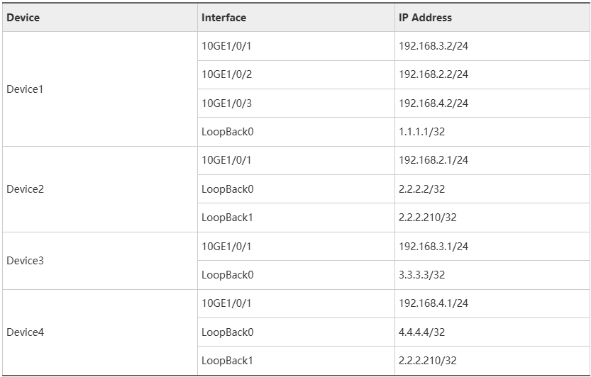
To complete the configuration, you need the following data:
- VMs’ VLAN IDs (10 and 20)
- IP addresses of interfaces connecting devices
- BD IDs (10 and 20)
- VNI IDs (10 and 20)
- VNI ID (5010) in a VPN instance
- RDs and RTs of EVPN and VPN instances
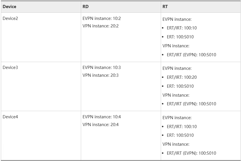

The configuration principles of RTs for the VPN instance and EVPN instance are described in figure above. In this example, you need to pay attention to the following points:
- For a VPN instance, you need to configure ERT Y and IRT Y with the EVPN parameter to enable route leaking into peer EVPN instances for host route generation. If route leaking into common L3VPN instances is required, configure common ERTs and IRTs.
- For an EVPN instance, apart from ERT A, ERT B, IRT A, and IRT B for two BDs, you also need to configure ERT Y for route iteration with a VPN instance. Generally, you do not need to configure IRT Y. If IRT Y is configured, the EVPN instances in different BDs flood MAC addresses to each other.
Procedure
- Configure an EBGP routing protocol.
# Configure Device1. Repeat this step for Device2, Device3, and Device4.
<HUAWEI> system-view
[~HUAWEI] sysname Device1
[*HUAWEI] commit
[~Device1] interface loopback 0
[*Device1-LoopBack0] ip address 1.1.1.1 32
[*Device1-LoopBack0] quit
[*Device1] interface 10ge 1/0/1
[*Device1-10GE1/0/1] undo portswitch
[*Device1-10GE1/0/1] ip address 192.168.3.2 24
[*Device1-10GE1/0/1] quit
[*Device1] interface 10ge 1/0/2
[*Device1-10GE1/0/2] undo portswitch
[*Device1-10GE1/0/2] ip address 192.168.2.2 24
[*Device1-10GE1/0/2] quit
[*Device1] interface 10ge 1/0/3
[*Device1-10GE1/0/3] undo portswitch
[*Device1-10GE1/0/3] ip address 192.168.4.2 24
[*Device1-10GE1/0/3] quit
[*Device1] bgp 100
[*Device1-bgp] router-id 1.1.1.1
[*Device1-bgp] peer 192.168.2.1 as-number 200
[*Device1-bgp] peer 192.168.3.1 as-number 300
[*Device1-bgp] peer 192.168.4.1 as-number 200
[*Device1-bgp] network 1.1.1.1 32
[*Device1-bgp] quit
[*Device1] commit
As Device 2 and Device 4 both belong to AS 200, to ensure that the two devices can notify each other of BGP routes, run the peer 192.168.2.2 allow-as-loop command on Device 2 and the peer 192.168.4.2 allow-as-loop command on Device 4
- Configure the VXLAN tunnel mode and enable the VXLAN ACL extension function. (This step only needs to be performed on the CE6870EI.)
# Configure Device2. Repeat this step for Device3 and Device4.
[~Device2] ip tunnel mode vxlan
[*Device2] assign forward nvo3 acl extend enable
[*Device2] commit
After modifying the VXLAN tunnel mode or enabling the VXLAN ACL extension function, you need to save the configuration and restart the device to make the configuration take effect. You can restart the device immediately or after completing all the configurations.
- Configure V-STP-based M-LAG between Device2 and Device4.
If the link through which Device2 is uplink connected to the VXLAN network fails, Device2 discards all received user traffic because no uplink outbound interface is available. You can configure a Monitor Link group to associate the uplink and downlink interfaces of Device2. When the uplink outbound interface of Device2 becomes Down, the downlink interface also becomes Down. Then user traffic will not be forwarded or discarded by Device2.
Create an Eth-Trunk and add physical Ethernet interfaces to the Eth-Trunk.
An uplink interface of a server connected to a switch needs to be bound to an aggregated link and the link aggregation mode of the server needs to be consistent with that of the switch.
# Create an Eth-Trunk in LACP mode on Device2 and add physical Ethernet interfaces to the Eth-Trunk. Repeat this step for Device4.
[~Device2] interface eth-trunk 1
[*Device2-Eth-Trunk1] mode lacp-static
[*Device2-Eth-Trunk1] trunkport 10ge 1/0/3
[*Device2-Eth-Trunk1] trunkport 10ge 1/0/4
[*Device2-Eth-Trunk1] quit
[*Device2] interface eth-trunk 10
[*Device2-Eth-Trunk10] mode lacp-static
[*Device2-Eth-Trunk10] trunkport 10ge 1/0/2
[*Device2-Eth-Trunk10] quit
[*Device2] commit
Configure V-STP on Device2 and Device4.
# Configure Device2. Repeat this step for Device4.
[~Device2] stp mode rstp
[*Device2] stp v-stp enable
[*Device2] commit
Configure a DFS group on Device2 and Device4, respectively.
# Configure Device2. Repeat this step for Device4.
[~Device2] dfs-group 1
[*Device2-dfs-group-1] dual-active detection enhanced enable
[*Device2-dfs-group-1] source ip 2.2.2.2 peer 4.4.4.4
[*Device2-dfs-group-1] quit
[*Device2] commit
Configure a link between Device2 and Device4 as the peer link.
# Configure Device2. Repeat this step for Device4.
[~Device2] interface eth-trunk 1
[~Device2-Eth-Trunk1] peer-link 1
[*Device2-Eth-Trunk1] quit
[*Device2] commit
Bind the user-side Eth-Trunk to the DFS group on Device2 and Device4.
# Configure Device2. Repeat this step for Device4.
[~Device2] interface eth-trunk 10
[~Device2-Eth-Trunk10] dfs-group 1 m-lag 1
[*Device2-Eth-Trunk10] stp edged-port enable
[*Device2-Eth-Trunk10] quit
[*Device2] commit- Configure a service access point on Device2, Device3, and Device4.
# Configure Device2. Repeat this step for Device3 and Device4.
[~Device2] bridge-domain 10
[*Device2-bd10] quit
[*Device2] interface eth-trunk 10.1 mode l2
[*Device2-Eth-Trunk10.1] encapsulation dot1q vid 10
[*Device2-Eth-Trunk10.1] bridge-domain 10
[*Device2-Eth-Trunk10.1] quit
[*Device2] commit- Configure EVPN as the VXLAN control plane.
# Configure Device1. Repeat this step for Device2, Device3, and Device4.
[~Device1] evpn-overlay enable
[*Device1] commit- Specify Device2, Device3, and Device4 as BGP EVPN peers for Device1 and configure them as RR clients.
# Specify BGP EVPN peers for Device1.
[~Device1] bgp 100 instance evpn1
[*Device1-bgp-instance-evpn1] router-id 1.1.1.1
[*Device1-bgp-instance-evpn1] peer 2.2.2.2 as-number 100
[*Device1-bgp-instance-evpn1] peer 2.2.2.2 connect-interface LoopBack0
[*Device1-bgp-instance-evpn1] peer 3.3.3.3 as-number 100
[*Device1-bgp-instance-evpn1] peer 3.3.3.3 connect-interface LoopBack0
[*Device1-bgp-instance-evpn1] peer 4.4.4.4 as-number 100
[*Device1-bgp-instance-evpn1] peer 4.4.4.4 connect-interface LoopBack0
[*Device1-bgp-instance-evpn1] l2vpn-family evpn
[*Device1-bgp-instance-evpn1-af-evpn] peer 2.2.2.2 enable
Warning: This operation will reset the peer session. Continue? [Y/N]: y
[*Device1-bgp-instance-evpn1-af-evpn] peer 2.2.2.2 reflect-client
[*Device1-bgp-instance-evpn1-af-evpn] peer 3.3.3.3 enable
Warning: This operation will reset the peer session. Continue? [Y/N]: y
[*Device1-bgp-instance-evpn1-af-evpn] peer 3.3.3.3 reflect-client
[*Device1-bgp-instance-evpn1-af-evpn] peer 4.4.4.4 enable
Warning: This operation will reset the peer session. Continue? [Y/N]: y
[*Device1-bgp-instance-evpn1-af-evpn] peer 4.4.4.4 reflect-client
[*Device1-bgp-instance-evpn1-af-evpn] undo policy vpn-target
[*Device1-bgp-instance-evpn1-af-evpn] quit
[*Device1-bgp-instance-evpn1] quit
[*Device1] commit- Specify Device1 as an IBGP EVPN peer for Device2, Device3, and Device4.
# Specify Device1 as a BGP EVPN peer for Device2. Repeat this step for Device3 and Device4.
[~Device2] bgp 100 instance evpn1
[*Device2-bgp-instance-evpn1] router-id 2.2.2.2
[*Device2-bgp-instance-evpn1] peer 1.1.1.1 as-number 100
[*Device2-bgp-instance-evpn1] peer 1.1.1.1 connect-interface LoopBack0
[*Device2-bgp-instance-evpn1] l2vpn-family evpn
[*Device2-bgp-instance-evpn1-af-evpn] peer 1.1.1.1 enable
Warning: This operation will reset the peer session. Continue? [Y/N]: y
[*Device2-bgp-instance-evpn1-af-evpn] quit
[*Device2-bgp-instance-evpn1] quit
[*Device2] commit- Configure VPN and EVPN instances on Device2, Device3, and Device4.
# Configure VPN and EVPN instances on Device2. Repeat this step for Device3 and Device4.
[~Device2] ip vpn-instance vpn1
[*Device2-vpn-instance-vpn1] vxlan vni 5010
[*Device2-vpn-instance-vpn1] ipv4-family
[*Device2-vpn-instance-vpn1-af-ipv4] route-distinguisher 20:2
[*Device2-vpn-instance-vpn1-af-ipv4] vpn-target 100:5010 evpn
[*Device2-vpn-instance-vpn1-af-ipv4] quit
[*Device2-vpn-instance-vpn1] quit
[*Device2] bridge-domain 10
[*Device2-bd10] vxlan vni 10
[*Device2-bd10] evpn
[*Device2-bd10-evpn] route-distinguisher 10:2
[*Device2-bd10-evpn] vpn-target 100:10
[*Device2-bd10-evpn] vpn-target 100:5010 export-extcommunity
[*Device2-bd10-evpn] quit
[*Device2-bd10] quit
[*Device2] commit- Configure an ingress replication list on Device2, Device3, and Device4.
# Configure Device2. Repeat this step for Device3 and Device4. You do not need to configure a MAC address for the NVE interface of Device3.
[~Device2] interface nve 1
[*Device2-Nve1] source 2.2.2.210
[*Device2-Nve1] mac-address 0000-5e00-0101
[*Device2-Nve1] vni 10 head-end peer-list protocol bgp
[*Device2-Nve1] quit
[*Device2] commit
Ensure that the IP addresses and MAC addresses of the NVE interfaces on Device2 and Device4 are the same, as they are dual-active gateways.
- Configure Device2, Device3, and Device4 as Layer 3 VXLAN gateways.
# Configure a service loopback interface on Device2. Repeat this step for Device3 and Device4. (This step only needs to be performed on the CE8850EI.)
[~Device2] interface eth-trunk 2
[*Device2-Eth-Trunk2] service type tunnel
[*Device2-Eth-Trunk2] quit
[*Device2] interface 10ge 1/0/5
[*Device2-10GE1/0/5] eth-trunk 2
[*Device2-10GE1/0/5] quit
[*Device2] commit
The member interfaces must be idle physical interfaces that do not transmit services. Ensure that the Eth-Trunk bandwidth is at least twice the bandwidth required for transmitting VXLAN Layer 3 gateway traffic. For example, if traffic is sent from users to the gateway across the VXLAN network at a rate of 10 Gbit/s, add two 10GE interface to the Eth-Trunk that you want to use as the service loopback interface.
# Configure a Layer 3 VXLAN gateway on Device2. The configurations on Device3 and Device4 are similar to that on Device2, and are not mentioned here. The IP addresses of VBDIF interfaces on Device2 and Device3 must be on different network segments. Configure the same IP address and MAC address for the VBDIF interface of Device2 and Device4. You do not need to configure a MAC address for the VBDIF interface of Device3.
[~Device2] interface vbdif10
[*Device2-Vbdif10] ip binding vpn-instance vpn1
[*Device2-Vbdif10] ip address 10.1.1.1 255.255.255.0
[*Device2-Vbdif10] mac-address 0000-5e00-0102
[*Device2-Vbdif10] vxlan anycast-gateway enable
[*Device2-Vbdif10] arp collect host enable
[*Device2-Vbdif10] quit
[*Device2] commit
Ensure that the IP addresses and MAC addresses of the VBDIF interfaces on Device2 and Device4 are the same, as they are dual-active gateways.
- Configure BGP between Device1 and Device2, Device3, and Device4 respectively to advertise IRB routes.
# Configure Device1. The configurations of Device2, Device3, and Device4 are similar to the configuration of Device1, and are not mentioned here.
[~Device1] bgp 100 instance evpn1
[~Device1-bgp-instance-evpn1] l2vpn-family evpn
[~Device1-bgp-instance-evpn1-af-evpn] peer 2.2.2.2 advertise irb
[*Device1-bgp-instance-evpn1-af-evpn] peer 3.3.3.3 advertise irb
[*Device1-bgp-instance-evpn1-af-evpn] peer 4.4.4.4 advertise irb
[*Device1-bgp-instance-evpn1-af-evpn] quit
[*Device1-bgp-instance-evpn1] quit
[*Device1] commit- Configure BGP between Device2 and Device3 and between Device2 and Device4 to advertise IP prefix routes to peers.
# Configure Device2. Repeat this step for Device3 and Device4.
[~Device2] bgp 100 instance evpn1
[~Device2-bgp-instance-evpn1] ipv4-family vpn-instance vpn1
[*Device2-bgp-instance-evpn1-vpn1] import-route direct
[*Device2-bgp-instance-evpn1-vpn1] advertise l2vpn evpn
[*Device2-bgp-instance-evpn1-vpn1] quit
[*Device2-bgp-instance-evpn1] quit
[*Device2] commit- Verify the configuration.
After completing the configurations, run the display vxlan tunnel command on Device2, Device3, and Device4 to check VXLAN tunnel information. The following example shows the command output on Device2.
[~Device2] display vxlan tunnel
Number of vxlan tunnel : 1
Tunnel ID   Source                Destination           State  Type     Uptime
-----------------------------------------------------------------------------------
4026531841  2.2.2.210             3.3.3.3               up     dynamic  0032h21m
The tunnel comes Up only after a Layer 2 sub-interface on Device2, Device3, or Device4 is connected to a server. When there is no server connected to the device, the VXLAN tunnel state is not displayed because no IRB route is advertised.