
Configuring VXLAN in Centralized Gateway Mode in Huawei Fabric
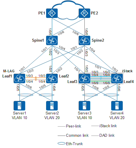
In this fabric topology data center network of an enterprise uses the centralized gateway deployment. Spine switches function as Layer 3 gateways, and leaf switches function as Layer 2 access devices to connect to servers. To ensure high reliability, spine switches use centralized all-active gateways, and leaf switches are deployed in stack mode or using M-LAG.
Configuration Roadmap
- Configure a routing protocol to ensure Layer 3 connectivity on the underlay network.
- Configure an M-LAG or a stack system to implement active-active server access.
- Configure BGP EVPN to establish VXLAN tunnels between leaf and spine switches.
Configuration Notes
- Run the assign forward nvo3 service extend enable command in the system view to enable the NVO3 service extension function.
- Run the assign forward nvo3 f-linecard compatibility enable command in the system view to ensure that VXLAN traffic can be forwarded when the card interoperability mode is non-enhanced mode.
Procedure
- Set up a stack between leaf switches. In this example, Leaf3 and Leaf4 set up a stack, and Leaf3 is the master switch.
# Configure Leaf3. After the configuration is complete, save the configuration and then restart Leaf3.
<HUAWEI> system-view
[~HUAWEI] sysname Leaf3
[*HUAWEI] commit
[~Leaf3] stack
[~Leaf3-stack] stack member 1 priority 150
[*Leaf3-stack] stack member 1 domain 10
[*Leaf3-stack] quit
[*Leaf3] interface stack-port 1/1
[*Leaf3-Stack-Port1/1] port member-group interface 10ge 1/0/3 to 1/0/4
Warning: After the configuration is complete,
1.The interface(s) (10GE1/0/3-1/0/4) will be converted to stack mode and be configured with the port crc-statistics trigger error-down command if the configuration does not exist.
2.The interface(s) may go Error-Down (crc-statistics) because there is no shutdown configuration on the interfaces.Continue? [Y/N]: y
[*Leaf3-Stack-Port1/1] quit
[*Leaf3] commit
[~Leaf3] quit
<Leaf3> save
Warning: The current configuration will be written to the device. Continue? [Y/N]: y
<Leaf3> reboot
Warning: The system will reboot. Continue? [Y/N]: y
# Configure Leaf4. After the configuration is complete, save the configuration and then restart Leaf4.
<HUAWEI> system-view
[~HUAWEI] sysname Leaf4
[*HUAWEI] commit
[~Leaf4] stack
[*Leaf4-stack] stack member 1 domain 10
[*Leaf4-stack] stack member 1 renumber 2 inherit-config
Warning: The stack configuration of member ID 1 will be inherited to member ID 2 after the device resets. Continue? [Y/N]: y
[*Leaf4-stack] quit
[*Leaf4] interface stack-port 1/1
[*Leaf4-Stack-Port1/1] port member-group interface 10ge 1/0/3 to 1/0/4
Warning: After the configuration is complete,
1.The interface(s) (10GE1/0/3-1/0/4) will be converted to stack mode and be configured with the port crc-statistics trigger error-down command if the configuration does not exist.
2.The interface(s) may go Error-Down (crc-statistics) because there is no shutdown configuration on the interfaces.Continue? [Y/N]: y
[*Leaf4-Stack-Port1/1] quit
[*Leaf4] commit
[~Leaf4] quit
<Leaf4> save
Warning: The current configuration will be written to the device. Continue? [Y/N]: y
<Leaf4> reboot
Warning: The system will reboot. Continue? [Y/N]: y
# Connect Leaf3 and Leaf4 using stack cables. Wait for several minutes and run the display stack command on Leaf3. After the stack is set up successfully, configure the DAD function and save the stack configuration.
<Leaf3> display stack
--------------------------------------------------------------------------------
MemberID Role     MAC              Priority   DeviceType         Description
--------------------------------------------------------------------------------
 1       Master   0004-9f31-d520   150        CE6850-48S6Q-HI
 2       Standby  0004-9f62-1f40   100        CE6850-48S6Q-HI
--------------------------------------------------------------------------------
<Leaf3> system-view
[~Leaf3] sysname iStack
[*Leaf3] commit
[~iStack] interface 10ge 1/0/9
[~iStack-10GE1/0/9] dual-active detect mode direct
Warning: The interface will block common data packets, except BPDU packets. Continue? [Y/N]: y
[*iStack-10GE1/0/9] quit
[*iStack] interface 10ge 2/0/9
[*iStack-10GE2/0/9] dual-active detect mode direct
Warning: The interface will block common data packets, except BPDU packets. Continue? [Y/N]: y
[*iStack-10GE2/0/9] commit
[~iStack-10GE2/0/9] return
<iStack> save
Warning: The current configuration will be written to the device. Continue? [Y/N]: y- Configure a routing protocol to implement Layer 3 connectivity on the underlay network.
# Configure Leaf1. Repeat this step for other switches.
<HUAWEI> system-view
[~HUAWEI] sysname Leaf1
[*HUAWEI] commit
[~Leaf1] interface 10ge 1/0/1
[~Leaf1-10GE1/0/1] undo portswitch
[*Leaf1-10GE1/0/1] ip address 192.168.1.2 24
[*Leaf1-10GE1/0/1] ospf network-type p2p
[*Leaf1-10GE1/0/1] quit
[*Leaf1] interface 10ge 1/0/2
[*Leaf1-10GE1/0/2] undo portswitch
[*Leaf1-10GE1/0/2] ip address 192.168.5.2 24
[*Leaf1-10GE1/0/2] ospf network-type p2p
[*Leaf1-10GE1/0/2] quit
[*Leaf1] interface loopback 1
[*Leaf1-LoopBack1] ip address 2.2.2.2 32
[*Leaf1-LoopBack1] quit
[*Leaf1] interface loopback 2
[*Leaf1-LoopBack2] ip address 6.6.6.6 32
[*Leaf1-LoopBack2] quit
[*Leaf1] ospf
[*Leaf1-ospf-1] area 0
[*Leaf1-ospf-1-area-0.0.0.0] network 192.168.1.0 0.0.0.255
[*Leaf1-ospf-1-area-0.0.0.0] network 192.168.5.0 0.0.0.255
[*Leaf1-ospf-1-area-0.0.0.0] network 2.2.2.2 0.0.0.0
[*Leaf1-ospf-1-area-0.0.0.0] network 6.6.6.6 0.0.0.0
[*Leaf1-ospf-1-area-0.0.0.0] quit
[*Leaf1-ospf-1] quit
[*Leaf1] commit
# After OSPF is configured, leaf and spine switches can learn the IP addresses of loopback interfaces of each other using OSPF and successfully ping each other.
- Set up an M-LAG between leaf switches. In this example, Leaf1 and Leaf2 set up an M-LAG.
# Configure Leaf1.
[~Leaf1] stp mode rstp
[*Leaf1] stp v-stp enable
[*Leaf1] dfs-group 1
[*Leaf1-dfs-group-1] source ip 6.6.6.6
[*Leaf1-dfs-group-1] priority 150
[*Leaf1-dfs-group-1] quit
[*Leaf1] interface eth-trunk 1
[*Leaf1-Eth-Trunk1] trunkport 10ge 1/0/3
[*Leaf1-Eth-Trunk1] trunkport 10ge 1/0/4
[*Leaf1-Eth-Trunk1] mode lacp-static
[*Leaf1-Eth-Trunk1] peer-link 1
[*Leaf1-Eth-Trunk1] quit
[*Leaf1] interface eth-trunk 2
[*Leaf1-Eth-Trunk2] trunkport 10ge 1/0/5
[*Leaf1-Eth-Trunk2] mode lacp-static
[*Leaf1-Eth-Trunk2] dfs-group 1 m-lag 1
[*Leaf1-Eth-Trunk2] stp edged-port enable
[*Leaf1-Eth-Trunk2] quit
[*Leaf1] interface eth-trunk 3
[*Leaf1-Eth-Trunk3] trunkport 10ge 1/0/6
[*Leaf1-Eth-Trunk3] mode lacp-static
[*Leaf1-Eth-Trunk3] dfs-group 1 m-lag 2
[*Leaf1-Eth-Trunk3] stp edged-port enable
[*Leaf1-Eth-Trunk3] quit
[*Leaf1] commit
[~Leaf1] monitor-link group 1
[*Leaf1-mtlk-group1] port 10ge 1/0/1 uplink
[*Leaf1-mtlk-group1] port 10ge 1/0/2 uplink
[*Leaf1-mtlk-group1] port eth-trunk 2 downlink 1
[*Leaf1-mtlk-group1] port eth-trunk 3 downlink 2
[*Leaf1-mtlk-group1] quit
[*Leaf1] commit
# Configure Leaf2.
[~Leaf2] stp mode rstp
[*Leaf2] stp v-stp enable
[*Leaf2] dfs-group 1
[*Leaf2-dfs-group-1] source ip 7.7.7.7
[*Leaf2-dfs-group-1] quit
[*Leaf2] interface eth-trunk 1
[*Leaf2-Eth-Trunk1] trunkport 10ge 1/0/3
[*Leaf2-Eth-Trunk1] trunkport 10ge 1/0/4
[*Leaf2-Eth-Trunk1] mode lacp-static
[*Leaf2-Eth-Trunk1] peer-link 1
[*Leaf2-Eth-Trunk1] quit
[*Leaf2] interface eth-trunk 2
[*Leaf2-Eth-Trunk2] mode lacp-static
[*Leaf2-Eth-Trunk2] trunkport 10ge 1/0/5
[*Leaf2-Eth-Trunk2] dfs-group 1 m-lag 1
[*Leaf2-Eth-Trunk2] stp edged-port enable
[*Leaf2-Eth-Trunk2] quit
[*Leaf2] interface eth-trunk 3
[*Leaf2-Eth-Trunk3] mode lacp-static
[*Leaf2-Eth-Trunk3] trunkport 10ge 1/0/6
[*Leaf2-Eth-Trunk3] dfs-group 1 m-lag 2
[*Leaf2-Eth-Trunk3] stp edged-port enable
[*Leaf2-Eth-Trunk3] quit
[*Leaf2] commit
[~Leaf2] monitor-link group 1
[*Leaf2-mtlk-group1] port 10ge 1/0/1 uplink
[*Leaf2-mtlk-group1] port 10ge 1/0/2 uplink
[*Leaf2-mtlk-group1] port eth-trunk 2 downlink 1
[*Leaf2-mtlk-group1] port eth-trunk 3 downlink 2
[*Leaf2-mtlk-group1] quit
[*Leaf2] commit- Configure BGP EVPN to establish a VXLAN tunnel.
Configure the VXLAN tunnel mode and enable the VXLAN ACL extension function. (This step only needs to be performed on the CE12800, CE16800 equipped with A series cards, CE6870EI, and CE6875EI.)
# Configure Spine1. Repeat this step for other switches.
[~Spine1] ip tunnel mode vxlan
[*Spine1] assign forward nvo3 acl extend enable
[*Spine1] commit- Configure a service access point.
# Configure Leaf1. Repeat this step for Leaf2.
[~Leaf1] bridge-domain 10
[*Leaf1-bd10] quit
[*Leaf1] bridge-domain 20
[*Leaf1-bd20] quit
[*Leaf1] interface eth-trunk 2.10 mode l2
[*Leaf1-Eth-Trunk2.10] encapsulation dot1q vid 10
[*Leaf1-Eth-Trunk2.10] bridge-domain 10
[*Leaf1-Eth-Trunk2.10] quit
[*Leaf1] interface eth-trunk 3.20 mode l2
[*Leaf1-Eth-Trunk3.20] encapsulation dot1q vid 20
[*Leaf1-Eth-Trunk3.20] bridge-domain 20
[*Leaf1-Eth-Trunk3.20] quit
[*Leaf1] commit
# Configure iStack.
[~iStack] bridge-domain 10
[*iStack-bd10] quit
[*iStack] bridge-domain 20
[*iStack-bd20] quit
[*iStack] interface eth-trunk 2
[*iStack-Eth-Trunk2] trunkport 10ge 1/0/5 2/0/5
[*iStack-Eth-Trunk2] mode lacp-static
[*iStack-Eth-Trunk2] stp edged-port enable
[*iStack-Eth-Trunk2] quit
[*iStack] interface eth-trunk 2.10 mode l2
[*iStack-Eth-Trunk2.10] encapsulation dot1q vid 10
[*iStack-Eth-Trunk2.10] bridge-domain 10
[*iStack-Eth-Trunk2.10] quit
[*iStack] interface eth-trunk 3
[*iStack-Eth-Trunk3] trunkport 10ge 1/0/6 2/0/6
[*iStack-Eth-Trunk3] mode lacp-static
[*iStack-Eth-Trunk3] stp edged-port enable
[*iStack-Eth-Trunk3] quit
[*iStack] interface eth-trunk 3.20 mode l2
[*iStack-Eth-Trunk3.20] encapsulation dot1q vid 20
[*iStack-Eth-Trunk3.20] bridge-domain 20
[*iStack-Eth-Trunk3.20] quit
[*iStack] commit- Establish BGP EVPN peer relationships. Spine1 and Spine2 function as RRs.
# Configure Spine1. Repeat this step for Spine2.
[~Spine1] evpn-overlay enable
[*Spine1] bgp 100
[*Spine1-bgp] peer 3.3.3.3 as-number 100
[*Spine1-bgp] peer 3.3.3.3 connect-interface LoopBack2
[*Spine1-bgp] peer 6.6.6.6 as-number 100
[*Spine1-bgp] peer 6.6.6.6 connect-interface LoopBack2
[*Spine1-bgp] peer 7.7.7.7 as-number 100
[*Spine1-bgp] peer 7.7.7.7 connect-interface LoopBack2
[*Spine1-bgp] l2vpn-family evpn
[*Spine1-bgp-af-evpn] peer 3.3.3.3 enable
Warning: This operation will reset the peer session. Continue? [Y/N]: y
[*Spine1-bgp-af-evpn] peer 3.3.3.3 reflect-client
[*Spine1-bgp-af-evpn] peer 6.6.6.6 enable
Warning: This operation will reset the peer session. Continue? [Y/N]: y
[*Spine1-bgp-af-evpn] peer 6.6.6.6 reflect-client
[*Spine1-bgp-af-evpn] peer 7.7.7.7 enable
Warning: This operation will reset the peer session. Continue? [Y/N]: y
[*Spine1-bgp-af-evpn] peer 7.7.7.7 reflect-client
[*Spine1-bgp-af-evpn] undo policy vpn-target
[*Spine1-bgp-af-evpn] quit
[*Spine1-bgp] quit
[*Spine1] commit
# Configure Leaf1. Repeat this step for Leaf2 and iStack
[~Leaf1] evpn-overlay enable
[*Leaf1] bgp 100
[*Leaf1-bgp] peer 4.4.4.4 as-number 100
[*Leaf1-bgp] peer 4.4.4.4 connect-interface LoopBack2
[*Leaf1-bgp] peer 5.5.5.5 as-number 100
[*Leaf1-bgp] peer 5.5.5.5 connect-interface LoopBack2
[*Leaf1-bgp] l2vpn-family evpn
[*Leaf1-bgp-af-evpn] peer 4.4.4.4 enable
Warning: This operation will reset the peer session. Continue? [Y/N]: y
[*Leaf1-bgp-af-evpn] peer 5.5.5.5 enable
Warning: This operation will reset the peer session. Continue? [Y/N]: y
[*Leaf1-bgp-af-evpn] quit
[*Leaf1-bgp] quit
[*Leaf1] commit- Configure EVPN instances and the ingress replication function.
# Configure Spine1. Repeat this step for other switches.
[~Spine1] bridge-domain 10
[~Spine1-bd10] vxlan vni 10
[*Spine1-bd10] evpn
[*Spine1-bd10-evpn] route-distinguisher 4.4.4.4:10
[*Spine1-bd10-evpn] vpn-target 0:10
[*Spine1-bd10-evpn] quit
[*Spine1-bd10] quit
[*Spine1] bridge-domain 20
[*Spine1-bd20] vxlan vni 20
[*Spine1-bd20] evpn
[*Spine1-bd20-evpn] route-distinguisher 4.4.4.4:20
[*Spine1-bd20-evpn] vpn-target 0:20
[*Spine1-bd20-evpn] quit
[*Spine1-bd20] quit
[*Spine1] interface nve 1
[*Spine1-Nve1] source 1.1.1.1 //Leaf1 and Leaf2 set up an M-LAG active-active system. The IP addresses of NVE interfaces on the two devices must be the same.
[*Spine1-Nve1] vni 10 head-end peer-list protocol bgp
[*Spine1-Nve1] vni 20 head-end peer-list protocol bgp
[*Spine1-Nve1] quit
[*Spine1] commit- Configure service loopback interfaces on Spine1 and Spine2. (This step only needs to be performed on the CE6850HI, CE6850U-HI, CE6851HI, CE6860EI, CE7850EI, CE8850EI, and CE8860EI.)
[~Spine1] interface eth-trunk 10
[*Spine1-Eth-Trunk10] trunkport 10ge 1/0/10 to 1/0/11
[*Spine1-Eth-Trunk10] service type tunnel
[*Spine1-Eth-Trunk10] quit
[*Spine1] commit- Configure all-active gateways on Spine1 and Spine2.
# Configure Spine1.
[~Spine1] ip vpn-instance vpn1
[*Spine1-vpn-instance-vpn1] ipv4-family
[*Spine1-vpn-instance-vpn1-af-ipv4] route-distinguisher 4.4.4.4:1
[*Spine1-vpn-instance-vpn1-af-ipv4] vpn-target 0:1
[*Spine1-vpn-instance-vpn1-af-ipv4] quit
[*Spine1-vpn-instance-vpn1] quit
[*Spine1] interface vbdif 10
[*Spine1-Vbdif10] ip binding vpn-instance vpn1
[*Spine1-Vbdif10] ip address 10.1.1.1 24 //Spine1 and Spine2 function as all-active gateways. The IP addresses and MAC addresses of the VBDIF interfaces on the two devices must be the same.
[*Spine1-Vbdif10] mac-address 0000-5e00-0101
[*Spine1-Vbdif10] quit
[*Spine1] interface vbdif 20
[*Spine1-Vbdif20] ip binding vpn-instance vpn1
[*Spine1-Vbdif20] ip address 10.1.2.1 24
[*Spine1-Vbdif20] mac-address 0000-5e00-0102
[*Spine1-Vbdif20] quit
[*Spine1] dfs-group 1
[*Spine1-dfs-group-1] source ip 4.4.4.4
[*Spine1-dfs-group-1] active-active-gateway
[*Spine1-dfs-group-1-active-active-gateway] peer 5.5.5.5
[*Spine1-dfs-group-1-active-active-gateway] quit
[*Spine1-dfs-group-1] quit
[*Spine1] commit- Configure static routes on Spine1 and Spine2 to implement north-south traffic transmission.
# Configure Spine1. Repeat this step for Spine2.
[~Spine1] interface 10ge 1/0/5
[~Spine1-10GE1/0/5] undo portswitch
[*Spine1-10GE1/0/5] ip address 10.1.10.1 24
[*Spine1-10GE1/0/5] quit
[~Spine1] interface 10ge 1/0/6
[~Spine1-10GE1/0/6] undo portswitch
[*Spine1-10GE1/0/6] ip address 10.1.20.1 24
[*Spine1-10GE1/0/6] quit
[*Spine1] ip route-static 0.0.0.0 0.0.0.0 10.1.10.2 //Configure a static route to a PE on the public network.
[*Spine1] ip route-static 0.0.0.0 0.0.0.0 10.1.20.2
[*Spine1] ip route-static 10.1.1.0 24 vpn-instance vpn1 //Configure a static route to the server network segment with the next hop being the VPN instance.
[*Spine1] ip route-static 10.1.2.0 24 vpn-instance vpn1
[*Spine1] ip route-static vpn-instance vpn1 0.0.0.0 0.0.0.0 public //Configure a static route of the VPN instance with the next hop being the public network instance.
[*Spine1] interface eth-trunk 10   //If a static route of which only a VPN instance is specified as the next hop (without any outbound interface or next-hop address specified) is configured on switches excluding the CE16800, CE12800, CE12800E (configured with ED-E, EG-E, and EGA-E series cards), CE5880EI, CE6870EI, CE6875EI, CE6881, CE5881, CE6881K, CE6881E, CE6863, CE6863E, CE6863K, and CE6880EI, you need to configure a service loopback interface.
[*Spine1-Eth-Trunk10] trunkport 10ge 1/0/10 to 1/0/11
[*Spine1-Eth-Trunk10] service type tunnel
[*Spine1-Eth-Trunk10] quit
[*Spine1] commit
Verifying the Configuration
Run the display vxlan tunnel command to check the VXLAN tunnel information. The following example shows the command output on Spine1.
[~Spine1] display vxlan tunnel
Number of vxlan tunnel : 2
Tunnel ID   Source                Destination           State  Type     Uptime
-----------------------------------------------------------------------------------
4026531841  1.1.1.1               2.2.2.2               up     dynamic  0035h21m
4026531842  1.1.1.1               3.3.3.3               up     dynamic  0036h21m
The preceding information indicates that servers can communicate.
Full Configuration Files
- Spine1 configuration file
#
sysname Spine1
#
assign forward nvo3 acl extend enable   //This step only needs to be performed on the CE12800, CE16800 equipped with A series cards, CE6870EI, and CE6875EI.
#
dfs-group 1
 source ip 4.4.4.4
 #
 active-active-gateway
  peer 5.5.5.5
#
evpn-overlay enable
#
ip vpn-instance vpn1
 ipv4-family
  route-distinguisher 4.4.4.4:1
  vpn-target 0:1 export-extcommunity
  vpn-target 0:1 import-extcommunity
#
bridge-domain 10
 vxlan vni 10
 evpn
  route-distinguisher 4.4.4.4:10
  vpn-target 0:10 export-extcommunity
  vpn-target 0:10 import-extcommunity
#
bridge-domain 20
 vxlan vni 20
 evpn
  route-distinguisher 4.4.4.4:20
  vpn-target 0:20 export-extcommunity
  vpn-target 0:20 import-extcommunity
#
interface Vbdif10
 ip binding vpn-instance vpn1
 ip address 10.1.1.1 255.255.255.0
 mac-address 0000-5e00-0101
#
interface Vbdif20
 ip binding vpn-instance vpn1
 ip address 10.1.2.1 255.255.255.0
 mac-address 0000-5e00-0102
#
interface Eth-Trunk10    //This step only needs to be performed on switches excluding the CE16800, CE12800, CE12800E (configured with ED-E, EG-E, and EGA-E series cards), CE5880EI, CE6870EI, CE6875EI, CE6881, CE5881, CE6881K, CE6881E, CE6863, CE6863E, CE6863K, and CE6880EI.
 service type tunnel
#
interface 10GE1/0/1
 undo portswitch
 ip address 192.168.1.1 255.255.255.0
 ospf network-type p2p
#
interface 10GE1/0/2
 undo portswitch
 ip address 192.168.2.1 255.255.255.0
 ospf network-type p2p
#
interface 10GE1/0/3
 undo portswitch
 ip address 192.168.3.1 255.255.255.0
 ospf network-type p2p
#
interface 10GE1/0/4
 undo portswitch
 ip address 192.168.4.1 255.255.255.0
 ospf network-type p2p
#
interface 10GE1/0/5
 undo portswitch
 ip address 10.1.10.1 255.255.255.0
#
interface 10GE1/0/6
 undo portswitch
 ip address 10.1.20.1 255.255.255.0
#
interface 10GE1/0/10    //This step only needs to be performed on switches excluding the CE16800, CE12800, CE12800E (configured with ED-E, EG-E, and EGA-E series cards), CE5880EI, CE6870EI, CE6875EI, CE6881, CE5881, CE6881K, CE6881E, CE6863, CE6863E, CE6863K, and CE6880EI.
 eth-trunk 10
#
interface 10GE1/0/11    //This step only needs to be performed on switches excluding the CE16800, CE12800, CE12800E (configured with ED-E, EG-E, and EGA-E series cards), CE5880EI, CE6870EI, CE6875EI, CE6881, CE5881, CE6881K, CE6881E, CE6863, CE6863E, CE6863K, and CE6880EI.
 eth-trunk 10
#
interface LoopBack1
 ip address 1.1.1.1 255.255.255.255
#
interface LoopBack2
 ip address 4.4.4.4 255.255.255.255
#
interface Nve1
 source 1.1.1.1
 vni 10 head-end peer-list protocol bgp
 vni 20 head-end peer-list protocol bgp
#
bgp 100
 peer 3.3.3.3 as-number 100
 peer 3.3.3.3 connect-interface LoopBack2
 peer 6.6.6.6 as-number 100
 peer 6.6.6.6 connect-interface LoopBack2
 peer 7.7.7.7 as-number 100
 peer 7.7.7.7 connect-interface LoopBack2
 #
 ipv4-family unicast
  peer 3.3.3.3 enable
  peer 6.6.6.6 enable
  peer 7.7.7.7 enable
 #
 l2vpn-family evpn
  undo policy vpn-target
  peer 3.3.3.3 enable
  peer 3.3.3.3 reflect-client
  peer 6.6.6.6 enable
  peer 6.6.6.6 reflect-client
  peer 7.7.7.7 enable
  peer 7.7.7.7 reflect-client
#
ospf 1
 area 0.0.0.0
  network 1.1.1.1 0.0.0.0
  network 4.4.4.4 0.0.0.0
  network 192.168.1.0 0.0.0.255
  network 192.168.2.0 0.0.0.255
  network 192.168.3.0 0.0.0.255
  network 192.168.4.0 0.0.0.255
#
ip route-static 0.0.0.0 0.0.0.0 10.1.10.2
ip route-static 0.0.0.0 0.0.0.0 10.1.20.2
ip route-static 10.1.1.0 255.255.255.0 vpn-instance vpn1
ip route-static 10.1.2.0 255.255.255.0 vpn-instance vpn1
ip route-static vpn-instance vpn1 0.0.0.0 0.0.0.0 public
#
return- Spine2 configuration file
#
sysname Spine2
#
assign forward nvo3 acl extend enable   //This step only needs to be performed on the CE12800, CE16800 equipped with A series cards, CE6870EI, and CE6875EI.
#
dfs-group 1
 source ip 5.5.5.5
 #
 active-active-gateway
  peer 4.4.4.4
#
evpn-overlay enable
#
ip vpn-instance vpn1
 ipv4-family
  route-distinguisher 5.5.5.5:1
  vpn-target 0:1 export-extcommunity
  vpn-target 0:1 import-extcommunity
#
bridge-domain 10
 vxlan vni 10
 evpn
  route-distinguisher 5.5.5.5:10
  vpn-target 0:10 export-extcommunity
  vpn-target 0:10 import-extcommunity
#
bridge-domain 20
 vxlan vni 20
 evpn
  route-distinguisher 5.5.5.5:20
  vpn-target 0:20 export-extcommunity
  vpn-target 0:20 import-extcommunity
#
interface Vbdif10
 ip binding vpn-instance vpn1
 ip address 10.1.1.1 255.255.255.0
 mac-address 0000-5e00-0101
#
interface Vbdif20
 ip binding vpn-instance vpn1
 ip address 10.1.2.1 255.255.255.0
 mac-address 0000-5e00-0102
#
interface Eth-Trunk10    //This step only needs to be performed on switches excluding the CE16800, CE12800, CE12800E (configured with ED-E, EG-E, and EGA-E series cards), CE5880EI, CE6870EI, CE6875EI, CE6881, CE5881, CE6881K, CE6881E, CE6863, CE6863E, CE6863K, and CE6880EI.
 service type tunnel
#
interface 10GE1/0/1
 undo portswitch
 ip address 192.168.5.1 255.255.255.0
 ospf network-type p2p
#
interface 10GE1/0/2
 undo portswitch
 ip address 192.168.6.1 255.255.255.0
 ospf network-type p2p
#
interface 10GE1/0/3
 undo portswitch
 ip address 192.168.7.1 255.255.255.0
 ospf network-type p2p
#
interface 10GE1/0/4
 undo portswitch
 ip address 192.168.8.1 255.255.255.0
 ospf network-type p2p
#
interface 10GE1/0/5
 undo portswitch
 ip address 10.1.30.1 255.255.255.0
#
interface 10GE1/0/6
 undo portswitch
 ip address 10.1.40.1 255.255.255.0
#
interface 10GE1/0/10    //This step only needs to be performed on switches excluding the CE16800, CE12800, CE12800E (configured with ED-E, EG-E, and EGA-E series cards), CE5880EI, CE6870EI, CE6875EI, CE6881, CE5881, CE6881K, CE6881E, CE6863, CE6863E, CE6863K, and CE6880EI.
 eth-trunk 10
#
interface 10GE1/0/11    //This step only needs to be performed on switches excluding the CE16800, CE12800, CE12800E (configured with ED-E, EG-E, and EGA-E series cards), CE5880EI, CE6870EI, CE6875EI, CE6881, CE5881, CE6881K, CE6881E, CE6863, CE6863E, CE6863K, and CE6880EI.
 eth-trunk 10
#
interface LoopBack1
 ip address 1.1.1.1 255.255.255.255
#
interface LoopBack2
 ip address 5.5.5.5 255.255.255.255
#
interface Nve1
 source 1.1.1.1
 vni 10 head-end peer-list protocol bgp
 vni 20 head-end peer-list protocol bgp
#
bgp 100
 peer 3.3.3.3 as-number 100
 peer 3.3.3.3 connect-interface LoopBack2
 peer 6.6.6.6 as-number 100
 peer 6.6.6.6 connect-interface LoopBack2
 peer 7.7.7.7 as-number 100
 peer 7.7.7.7 connect-interface LoopBack2
 #
 ipv4-family unicast
  peer 3.3.3.3 enable
  peer 6.6.6.6 enable
  peer 7.7.7.7 enable
 #
 l2vpn-family evpn
  undo policy vpn-target
  peer 3.3.3.3 enable
  peer 3.3.3.3 reflect-client
  peer 6.6.6.6 enable
  peer 6.6.6.6 reflect-client
  peer 7.7.7.7 enable
  peer 7.7.7.7 reflect-client
#
ospf 1
 area 0.0.0.0
  network 1.1.1.1 0.0.0.0
  network 5.5.5.5 0.0.0.0
  network 192.168.5.0 0.0.0.255
  network 192.168.6.0 0.0.0.255
  network 192.168.7.0 0.0.0.255
  network 192.168.8.0 0.0.0.255
#
ip route-static 0.0.0.0 0.0.0.0 10.1.30.2
ip route-static 0.0.0.0 0.0.0.0 10.1.40.2
ip route-static 10.1.1.0 255.255.255.0 vpn-instance vpn1
ip route-static 10.1.2.0 255.255.255.0 vpn-instance vpn1
ip route-static vpn-instance vpn1 0.0.0.0 0.0.0.0 public
#
return- Leaf1 configuration file
#
sysname Leaf1
#
assign forward nvo3 acl extend enable   //This step only needs to be performed on the CE12800, CE16800 equipped with A series cards, CE6870EI, and CE6875EI.
#
dfs-group 1
 priority 150
 source ip 6.6.6.6
#
stp mode rstp
stp v-stp enable
#
evpn-overlay enable
#
bridge-domain 10
 vxlan vni 10
 evpn
  route-distinguisher 6.6.6.6:10
  vpn-target 0:10 export-extcommunity
  vpn-target 0:10 import-extcommunity
#
bridge-domain 20
 vxlan vni 20
 evpn
  route-distinguisher 6.6.6.6:20
  vpn-target 0:20 export-extcommunity
  vpn-target 0:20 import-extcommunity
#
interface Eth-Trunk1
 mode lacp-static
 peer-link 1
#
interface Eth-Trunk2
 stp edged-port enable
 mode lacp-static
 dfs-group 1 m-lag 1
#
interface Eth-Trunk2.10 mode l2
 encapsulation dot1q vid 10
 bridge-domain 10
#
interface Eth-Trunk3
 stp edged-port enable
 mode lacp-static
 dfs-group 1 m-lag 2
#
interface Eth-Trunk3.20 mode l2
 encapsulation dot1q vid 20
 bridge-domain 20
#
interface 10GE1/0/1
 undo portswitch
 ip address 192.168.1.2 255.255.255.0
 ospf network-type p2p
#
interface 10GE1/0/2
 undo portswitch
 ip address 192.168.5.2 255.255.255.0
 ospf network-type p2p
#
interface 10GE1/0/3
 eth-trunk 1
#
interface 10GE1/0/4
 eth-trunk 1
#
interface 10GE1/0/5
 eth-trunk 2
#
interface 10GE1/0/6
 eth-trunk 3
#
interface LoopBack1
 ip address 2.2.2.2 255.255.255.255
#
interface LoopBack2
 ip address 6.6.6.6 255.255.255.255
#
interface Nve1
 source 2.2.2.2
 vni 10 head-end peer-list protocol bgp
 vni 20 head-end peer-list protocol bgp
#
monitor-link group 1
 port 10GE1/0/1 uplink
 port 10GE1/0/2 uplink
 port Eth-Trunk2 downlink 1
 port Eth-Trunk3 downlink 2
#
bgp 100
 peer 4.4.4.4 as-number 100
 peer 4.4.4.4 connect-interface LoopBack2
 peer 5.5.5.5 as-number 100
 peer 5.5.5.5 connect-interface LoopBack2
 #
 ipv4-family unicast
  peer 4.4.4.4 enable
  peer 5.5.5.5 enable
 #
 l2vpn-family evpn
  policy vpn-target
  peer 4.4.4.4 enable
  peer 5.5.5.5 enable
#
ospf 1
 area 0.0.0.0
  network 2.2.2.2 0.0.0.0
  network 6.6.6.6 0.0.0.0
  network 192.168.1.0 0.0.0.255
  network 192.168.5.0 0.0.0.255
#
return- Leaf2 configuration file
#
sysname Leaf2
#
assign forward nvo3 acl extend enable   //This step only needs to be performed on the CE12800, CE16800 equipped with A series cards, CE6870EI, and CE6875EI.
#
dfs-group 1
 source ip 7.7.7.7
#
stp mode rstp
stp v-stp enable
#
evpn-overlay enable
#
bridge-domain 10
 vxlan vni 10
 evpn
  route-distinguisher 7.7.7.7:10
  vpn-target 0:10 export-extcommunity
  vpn-target 0:10 import-extcommunity
#
bridge-domain 20
 vxlan vni 20
 evpn
  route-distinguisher 7.7.7.7:20
  vpn-target 0:20 export-extcommunity
  vpn-target 0:20 import-extcommunity
#
interface Eth-Trunk1
 mode lacp-static
 peer-link 1
#
interface Eth-Trunk2
 stp edged-port enable
 mode lacp-static
 dfs-group 1 m-lag 1
#
interface Eth-Trunk2.10 mode l2
 encapsulation dot1q vid 10
 bridge-domain 10
#
interface Eth-Trunk3
 stp edged-port enable
 mode lacp-static
 dfs-group 1 m-lag 2
#
interface Eth-Trunk3.20 mode l2
 encapsulation dot1q vid 20
 bridge-domain 20
#
interface 10GE1/0/1
 undo portswitch
 ip address 192.168.2.2 255.255.255.0
 ospf network-type p2p
#
interface 10GE1/0/2
 undo portswitch
 ip address 192.168.6.2 255.255.255.0
 ospf network-type p2p
#
interface 10GE1/0/3
 eth-trunk 1
#
interface 10GE1/0/4
 eth-trunk 1
#
interface 10GE1/0/5
 eth-trunk 2
#
interface 10GE1/0/6
 eth-trunk 3
#
interface LoopBack1
 ip address 2.2.2.2 255.255.255.255
#
interface LoopBack2
 ip address 7.7.7.7 255.255.255.255
#
interface Nve1
 source 2.2.2.2
 vni 10 head-end peer-list protocol bgp
 vni 20 head-end peer-list protocol bgp
#
monitor-link group 1
 port 10GE1/0/1 uplink
 port 10GE1/0/2 uplink
 port Eth-Trunk2 downlink 1
 port Eth-Trunk3 downlink 2
#
bgp 100
 peer 4.4.4.4 as-number 100
 peer 4.4.4.4 connect-interface LoopBack2
 peer 5.5.5.5 as-number 100
 peer 5.5.5.5 connect-interface LoopBack2
 #
 ipv4-family unicast
  peer 4.4.4.4 enable
  peer 5.5.5.5 enable
 #
 l2vpn-family evpn
  policy vpn-target
  peer 4.4.4.4 enable
  peer 5.5.5.5 enable
#
ospf 1
 area 0.0.0.0
  network 2.2.2.2 0.0.0.0
  network 7.7.7.7 0.0.0.0
  network 192.168.2.0 0.0.0.255
  network 192.168.6.0 0.0.0.255
#
return- iStack configuration file
#
sysname iStack
#
assign forward nvo3 acl extend enable   //This step only needs to be performed on the CE12800, CE16800 equipped with A series cards, CE6870EI, and CE6875EI.
#
evpn-overlay enable
#
bridge-domain 10
 vxlan vni 10
 evpn
  route-distinguisher 3.3.3.3:10
  vpn-target 0:10 export-extcommunity
  vpn-target 0:10 import-extcommunity
#
bridge-domain 20
 vxlan vni 20
 evpn
  route-distinguisher 3.3.3.3:20
  vpn-target 0:20 export-extcommunity
  vpn-target 0:20 import-extcommunity
#
stack
 #
 stack member 1 domain 10
 stack member 1 priority 150
 #
 stack member 2 domain 10
 #
interface Eth-Trunk2
 stp edged-port enable
 mode lacp-static
 #
interface Eth-Trunk2.10 mode l2
 encapsulation dot1q vid 10
 bridge-domain 10
#
interface Eth-Trunk3
 stp edged-port enable
 mode lacp-static
#
interface Eth-Trunk3.20 mode l2
 encapsulation dot1q vid 20
 bridge-domain 20
#
interface Stack-Port1/1
#
interface Stack-Port2/1
#
interface 10GE1/0/1
 undo portswitch
 ip address 192.168.3.2 255.255.255.0
 ospf network-type p2p
#
interface 10GE1/0/2
 undo portswitch
 ip address 192.168.7.2 255.255.255.0
 ospf network-type p2p
#
interface 10GE1/0/3
 port mode stack
 stack-port 1/1
 port crc-statistics trigger error-down
#
interface 10GE1/0/4
 port mode stack
 stack-port 1/1
 port crc-statistics trigger error-down
#
interface 10GE1/0/5
 eth-trunk 2
#
interface 10GE1/0/6
 eth-trunk 3
#
interface 10GE1/0/9
 dual-active detect mode direct
#
interface 10GE2/0/1
 undo portswitch
 ip address 192.168.4.2 255.255.255.0
 ospf network-type p2p
#
interface 10GE2/0/2
 undo portswitch
 ip address 192.168.8.2 255.255.255.0
 ospf network-type p2p
#
interface 10GE2/0/3
 port mode stack
 stack-port 2/1
 port crc-statistics trigger error-down
#
interface 10GE2/0/4
 port mode stack
 stack-port 2/1
 port crc-statistics trigger error-down
#
interface 10GE2/0/5
 eth-trunk 2
#
interface 10GE2/0/6
 eth-trunk 3
#
interface 10GE2/0/9
 dual-active detect mode direct
#
interface LoopBack1
 ip address 3.3.3.3 255.255.255.255
#
interface Nve1
 source 3.3.3.3
 vni 10 head-end peer-list protocol bgp
 vni 20 head-end peer-list protocol bgp
#
bgp 100
 peer 4.4.4.4 as-number 100
 peer 4.4.4.4 connect-interface LoopBack1
 peer 5.5.5.5 as-number 100
 peer 5.5.5.5 connect-interface LoopBack1
 #
 ipv4-family unicast
  peer 4.4.4.4 enable
  peer 5.5.5.5 enable
 #
 l2vpn-family evpn
  policy vpn-target
  peer 4.4.4.4 enable
  peer 5.5.5.5 enable
#
ospf 1
 area 0.0.0.0
  network 3.3.3.3 0.0.0.0
  network 192.168.3.0 0.0.0.255
  network 192.168.4.0 0.0.0.255
  network 192.168.7.0 0.0.0.255
  network 192.168.8.0 0.0.0.255
#
return